Stack Splice Tray

Part Number Description Certification Specification
35260412 STACK SPLICE TRAY KIT 12F FOR FIBER OPTIC RACK MOUNT

RoHS Compliant
ISO 9001, ISO14001

35260424 STACK SPLICE TRAY KIT 24F FOR FIBER OPTIC RACK MOUNT
35265050 STACK SPLICE TRAY KIT 36F FOR FIBER OPTIC RACK MOUNT
35260218 STACK SPLICE TRAY KIT 48F FOR FIBER OPTIC RACK MOUNT

General Characteristics

Product Type

Fiber Distribution Frame

Description

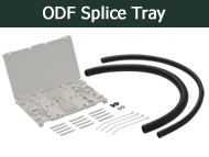
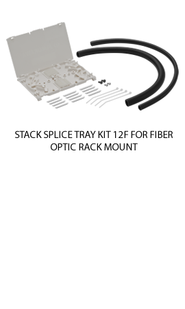
Set of accessories to accommodate optical splices in the optical shelves.
Composed by splice trays, plastic film protector, screws, splice protectors and
plastic clamps for fixing cables.
Available in kits for 12F, 24F, 36F and 48F optics.
Can be opened for both sides and should be used with splice protectors of 40mm.
(The splice protectors are already provided with the tray).

Compatibility

DIO A270, DIO B48, DIO A115, B144, HDMOD and DIOs BT32, BT36, BT24, BT48 and BT96.

Advantage

Recommended for internal use in internal optical shelves for use with fusion
splices;
Kit to 12, 24, 36 or 48 splices, expandable through stacking of the trays;
Trays made of plastic material;
By being stacked, the trays can be opened to either side, conferring flexibility
to the fusion system;
Splice holder switchable, allowing the accommodation of fusion splices,
mechanical splices, splitters, etc.;
Flexible design, allowing perfect accommodation of bare fibers and splices,
with radius of curvature proper and guides for reversal of fiber if necessary.

Positions Quantity

12, 24, 36 or 48 positions

Accessories Included

Tray to 12 fusions;
12 splice protectors 40mm;
Plastic clamps;
Numerical labels to identification;
Screws.


Technology Innovation and quality in certified and recognized products.

Optical Fibers


When it comes to long distance and transmission rate’s performance, optical cabling is the best. It is by far, a better choice than copper cabling. Installation of optical networks follow the same rules as those for buildings, datacenter or MDUs. The optical channel presented at the figure below is an example of performance measurement for any optical solution.


Aiming even higher transmission rates, different multimode fibers MM(50/125μm) were developed, such as OM3, OM4 and more recently OM5. These ibers are compatible with VCSEL, a semiconductor-based laser diode that allows higher taxes of transmission, within distances compatible with local networks. Among the fibers applied in critical environments or with high taxes of data transmission, OM5 should be highlighted, as it is the only one which bandwidth is characterized to be used with SWDW (Short Wavelength Division Multiplexing). The following table shows the performance of multimode optical fibers under the use of SWDM.


OM5 Multimode Fiber
The Wide band multimode optical fiber (WBMMF), optimized for SWDM application

The new generation of the 50 µm multimode fibers, known as OM5, comes to enlarge the performance from previous versions, allowing data traffic in rates such as 40G/100Gbps, for now. Besides being totally compatible with current application of Multimode fibers, the new model was developed in order to support and promote the use of SWDM, which operation and use is explained and depicted as it follows:


In order to establish minimum condition for performance of SWDM technology usage with multimode fibers, it is necessary to establish and determine the bandwidth necessity to transit all used wavelengths. The main differential of the OM5, when comparing with previous fibers, is this characterization.
Currently, the technology SWDM supports 4 wavelengths, that means an improvement of 4 times the transmission rate in face of conventional transmission. OM5 fiber is still under standardization phase, it is still awaiting for the creation of a norm, such as TIA- 942AAAE, to stablish specifications for its specific multimode optical fibers.


Single-Mode Fibers & Non-Zero Dispersion (NZD)

“Low Water Peak” (G.652.D) ---> Metropolitan and access networks.
It enables future expansion of the network for new users via CWDM in up to 16 channels. Fifty percent increase of the transmission capacity in relation to the conventional single-mode fibers. Low attenuation coefficient at the water absorption peak (1383±3 nm), assuring additional use of the E band (1360 to 1460 nm), as well as along the other transmission bands (1270 to 1610 nm)

“Bending Loss Insensitive” (G.657.A ---> FTTH Access networks (Fiber-To-The-Home) and local networks.
Low values of loss, due to curvature, along its entire transmission spectrum, from 1260 to 1625 nm. It allows bending at diameters up to 20 mm generating maximum loss of 0.5 dB at 1625nm and 0.2 dB at 1550 nm.


Related Certifications
   
  Certifications


ETL Listed


Related Products
   
responsive carousel
                 
    บริษัทใน กลุ่ม ฟูรูคาวา อิเล็คทริค     ช่องทางบริการด่วน   บริการลูกค้า  
  Furukawa Electric Co., Ltd. (Japan)     การรับประกันสินค้า   โทร : (662) 105-4057  
  Furukawa Electric LatAm (Brazil)     การฝึกอบรม   แฟกซ์ : (662) 632-1080  
  OFS Fitel, LLC. (USA)     ตัวแทนจำหน่ายอย่างเป็นทางการ   อีเมล์ : support@fecsa.co.th  
  FITEL (Global Site)     ตัวแทนผู้ติดตั้งที่ผ่านการรับรอง   แผนที่ : FECSA  
  Furukawa Electric Europe Ltd     Follow on Social Media      
         
 
Furukawa Electric Communications Southeast Asia Ltd.
191 Silom Complex Building, Unit C, 16th Fl., Silom Road, Kwaeng Silom, Khet Bangrak, Bangkok. 10500 Thailand.
Tel : +66 (0) 2-105-4057  Fax: +66 (0) 2632-1080